Skip to content
Protection Relay .com
Your Partner in Protection, SAS, and IEC 61850
Home
Courses
Contact
Blog
Get Started
Protection Relay .com
Your Partner in Protection, SAS, and IEC 61850
Toggle Menu
Author: Fatima
Busbar protection training package
By
Fatima
Hours
April 17, 2022
August 6, 2024
Generator Protection Training Package
By
Fatima
Hours
January 1, 2022
August 6, 2024
Reverse Busbar Blocking Scheme
By
Fatima
Hours
September 18, 2021
June 15, 2026
Testing and Commissioning of Protective Relays
By
Fatima
Hours
August 25, 2021
August 6, 2024
MiCOM Relays Training Package
By
Fatima
Hours
August 24, 2021
August 6, 2024
PSCAD Training for protection engineers
By
Fatima
Hours
August 20, 2021
June 15, 2026
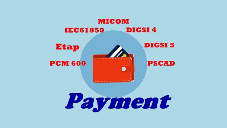
Payment
By
Fatima
Hours
July 28, 2021
June 15, 2026
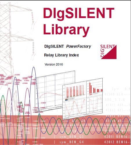
DIgSILENT Relay Library
By
Fatima
Hours
June 16, 2021
June 15, 2026
Full Video Training package
By
Fatima
Hours
May 27, 2021
June 15, 2026
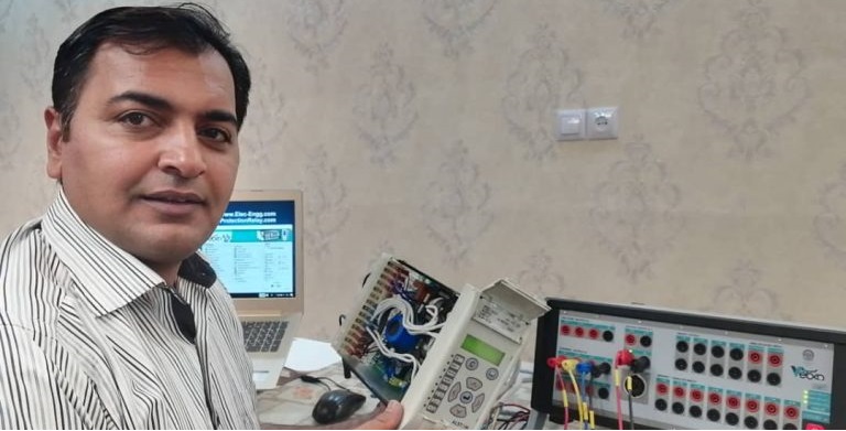
Protection Relay Training
By
Fatima
Hours
May 5, 2021
June 15, 2026
Page navigation
1
2
3
Next Page
Next
Scroll to top
Scroll to top
Home
Courses
Contact
Blog