Skip to content
Protection Relay .com
Your Partner in Protection, SAS, and IEC 61850
Home
Courses
Contact
Blog
Get Started
Protection Relay .com
Your Partner in Protection, SAS, and IEC 61850
Toggle Menu
Completed
Completed Training Package
IEC 61850 Video Training
By
Fatima
Hours
December 7, 2020
June 15, 2026
DIGSI 5 Video Training
By
Fatima
Hours
November 14, 2020
June 15, 2026
DIGSI 4 Training
By
Fatima
Hours
October 22, 2020
June 15, 2026
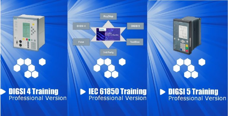
DIGSI & IEC 61850 Professional video training Package
By
Saeed
Hours
March 5, 2020
June 15, 2026
IEC 61850 Configurator Training
By
Saeed
Hours
March 2, 2020
June 15, 2026
DIGSI 5 Video Training
By
Saeed
Hours
March 2, 2020
June 15, 2026
Protected: DIGSI 4 Video Training
By
Saeed
Hours
March 2, 2020
June 15, 2026
Scroll to top
Scroll to top
Home
Courses
Contact
Blog