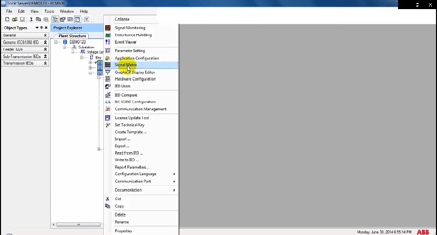
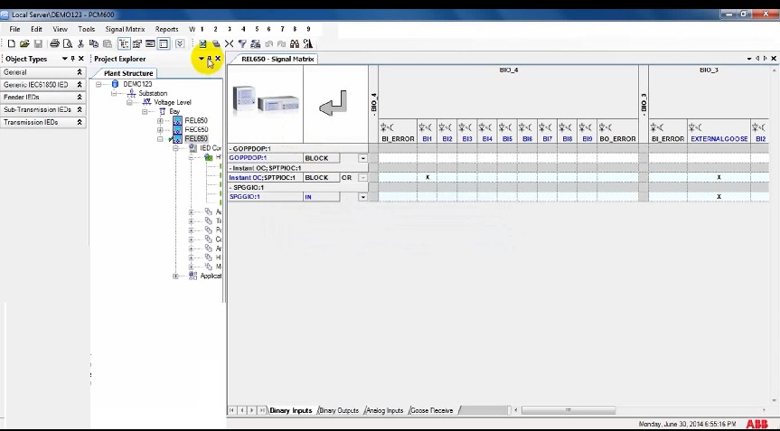
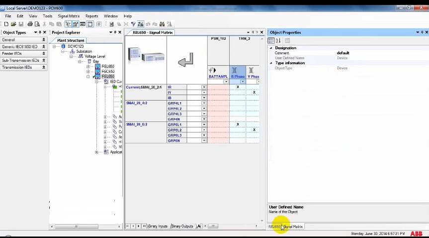
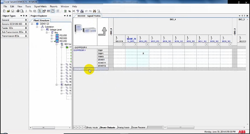
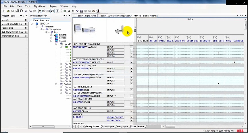
- Right-click on IED and select Signal Matrix
2. now we will export selected (Binary inputs/ Binary outputs/ Analog inputs/ goose receive) to excel
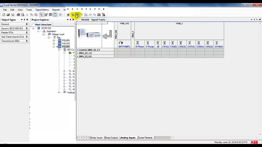
3. collapse all rows/ columns and expand all rows/ columns
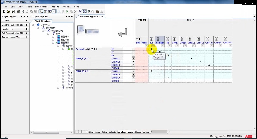
4. General filter and particular row/ column filter
b
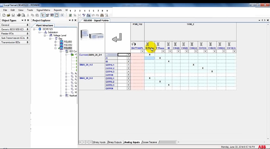
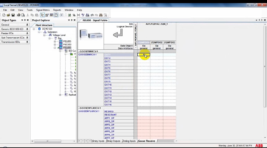
6. Map some goose receive signals by double click, create a connection between selected columns and rows.
7. Double click on the existing connection will disconnect the existing connection between the selected column and row.
8. Some redo and undo.
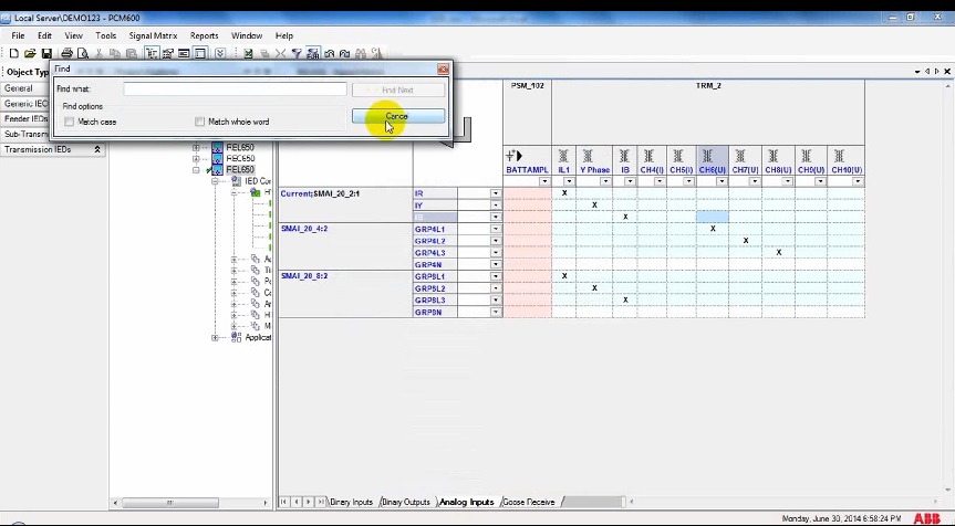
9. Try to find some signal using find. Find will Highlight the signal where it is.
10. Double click on a particular group of items in any rows or columns to hide or show.
11. Create an inverted signal in Binary outputs/inputs
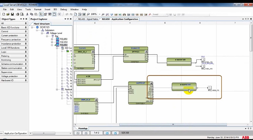
12. You can see a Glue logic inverter created because of mapping “I” in the signal matrix.
13. flip column text to horizontal/ vertical for binary inputs/ binary outputs/analog inputs/goose receive
These pictures are part of our supplementary files for ABB PCM 600 training that is mixed with Oral explanations to help you understand this course. These auxiliary files have been gathered and attached to our ABB PCM600 training course, you can get more information by
Contact us :
- saeed61850@gmail.com / info@elec-engg.com
- WhatsApp: +989129613659
Our completed Courses:
- IEC 61850 Configurator Training (4 Hrs)
- DIGSI 4 Offline Video Training (3 Hrs)
- DIGSI 5 Offline Video Training (7 Hrs)
- ETAP VIDEO Training (5.5)
- PSCAD Video Training (4 Hrs)
- PCM 600 Video Training (4 Hrs)
- MiCOM Relays Training Package (4 Hrs)
- Testing and Commissioning of Protective Relays
